Components Glossary
Every part in the kit: what it is, how to recognize it, whether direction matters, and where it's used.
Polarity key: 🔴 polarized — direction matters, can be damaged if reversed · ⚪ not polarized — either way is fine.
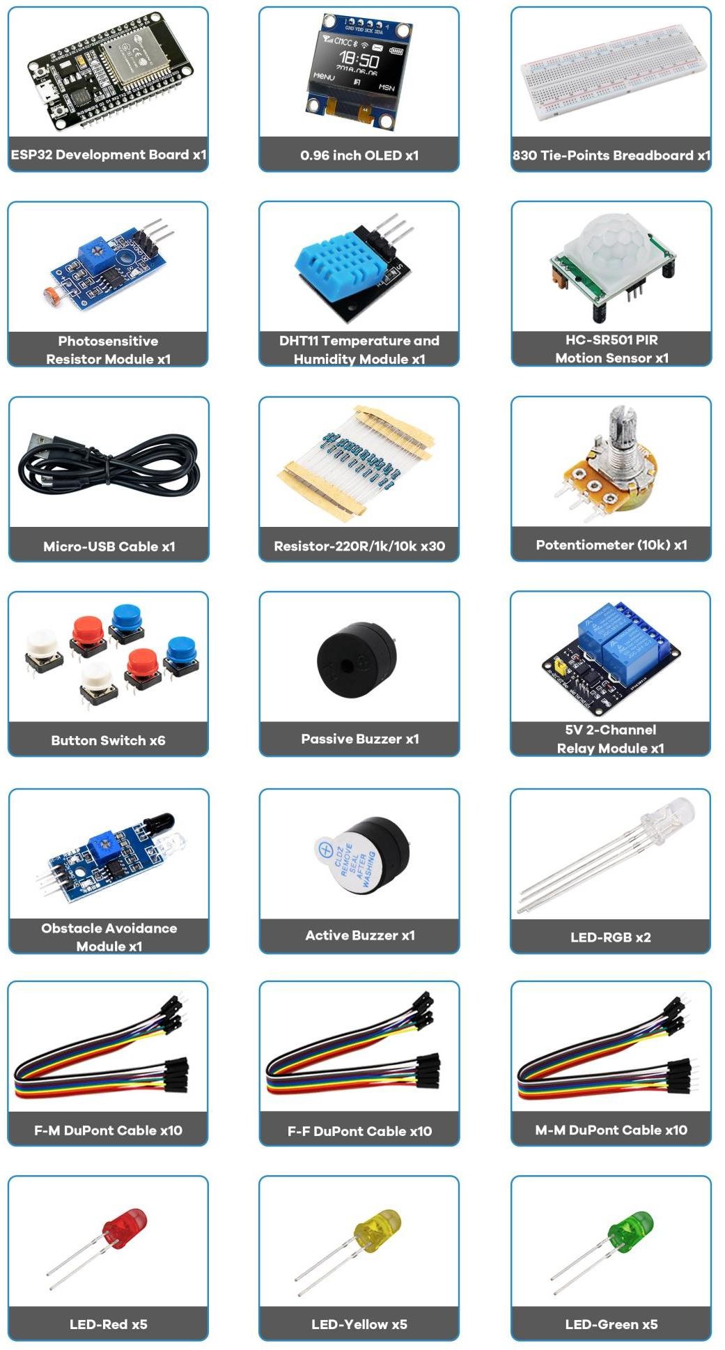
Core
| Part | What it is | How to identify | Polarity / notes | Used in |
|---|---|---|---|---|
| ESP32 DEVKIT V1 | The microcontroller — dual‑core + Wi‑Fi/BT | Black PCB, metal ESP‑WROOM‑32 can, micro‑USB, EN + BOOT | 🔴 logic is 3.3 V | All |
| Breadboard (830 pts) | Solderless build surface | White plastic, rows of holes + side rails | ⚪ rails = +/−; inner rows connect in 5s | All |
| Micro‑USB cable | Power + code upload | Standard micro‑USB | ⚪ use a data cable | All |
| Jumper wires (M‑M, M‑F, F‑F) | Connect points | Coloured wires with pins/sockets | ⚪ colour is for your clarity | All |
Outputs
| Part | What it is | How to identify | Polarity / notes | Used in |
|---|---|---|---|---|
| LED (red/yellow/green) | A diode that glows | 5 mm dome, one leg longer | 🔴 long leg = + ; needs 220 Ω | P1, P3, P5, P8 |
| RGB LED (common cathode) | Three LEDs in one | 4 legs; longest = shared cathode | 🔴 cathode → GND; anodes via 220 Ω | P6 |
| Active buzzer | Beeps when powered | Sealed case, often a + mark | 🔴 + → GPIO, − → GND | P4 |
| Passive buzzer | Tones only when fed a signal | Open PCB visible underneath | 🔴 driven by PWM / tone() | bonus |
| 5 V 2‑channel relay | Switch for bigger loads | Blue box(es), screw terminals + IN pins | 🔴 VCC=5 V; COM/NO/NC on load side | P7 |
Inputs & sensors
| Part | What it is | How to identify | Polarity / notes | Used in |
|---|---|---|---|---|
| Pushbutton | Momentary switch (digital in) | Small 4‑leg tactile button | ⚪ pair with a 10 kΩ pull resistor | P1, P8 |
| Potentiometer (10 kΩ) | Variable resistor → analog in | Knob with 3 legs | ⚪ outers to 3.3 V/GND, middle = wiper | P2 |
| DHT11 module | Temperature + humidity | Blue box, 3 pins (−, +, S) | 🔴 +→3.3 V, −→GND, S→data | P9 |
| HC‑SR501 PIR | Motion (infra‑red) sensor | White dome lens, two orange trimmers | 🔴 VCC=5 V, OUT = HIGH on motion | P4 |
| SSD1306 OLED (0.96″) | 128×64 I²C display | Small glass screen, 4 pins | 🔴 SDA 21, SCL 22, addr 0x3C | P10 |
| Photoresistor (LDR) module | Light sensor | PCB with a squiggly‑top sensor | 🔴 VCC/GND + analog/digital out | bonus |
| Obstacle‑avoidance module | IR proximity detector | PCB with two IR LEDs + trimmer | 🔴 VCC/GND + digital OUT | bonus |
Passive components
| Part | What it is | How to identify (5‑band) | Used in |
|---|---|---|---|
| Resistor 220 Ω | Limits current (LEDs) | Red·Red·Black·Black·Brown | LED projects |
| Resistor 1 kΩ | General purpose | Brown·Black·Black·Brown·Brown | as needed |
| Resistor 10 kΩ | Pull‑up / pull‑down | Brown·Black·Black·Red·Brown | P1, P8 |
Read 5‑band resistors with the tolerance band (Brown, ±1%) on the right. First band tells them apart — Red starts 220 Ω, Brown starts 1 kΩ and 10 kΩ. All resistors are ⚪ not polarized.
"Bonus" parts (not used by Projects 1–10)
The photoresistor, passive buzzer, and obstacle‑avoidance module aren't in the ten core projects, but you now know enough to try them: