Analog Inputs — Reading a Potentiometer
Measure a range of voltage (0–3.3 V) as a number 0–4095 with the ESP32's ADC.
⬇ Download the sketch
Save
Project_2_ESP32_Analog_Inputs.ino, then open it in the Arduino IDE (setup: Project 0b).
1 · Analog vs. digital, recapped
- A digital input sees only HIGH or LOW (Project 1).
- An analog input measures a continuous voltage 0–3.3 V and converts it to a number via the ADC.
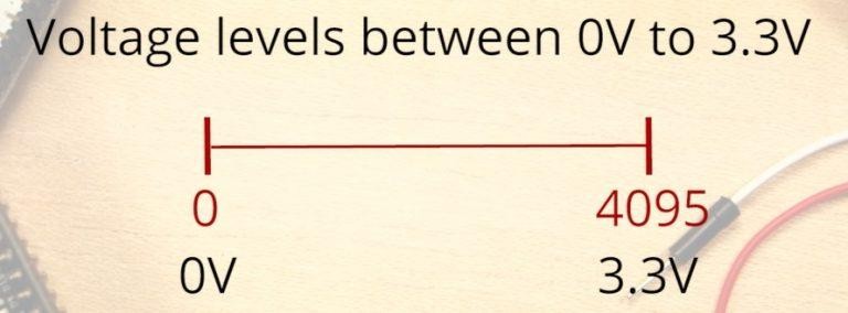
The ESP32 ADC is 12‑bit, so readings run 0 … 4095:
The ADC pin here
We use GPIO 4 ANALOG (ADC2, channel 0) — the same physical pin that was a digital input in Project 1, now used with analogRead().
For later: GPIO 4 is on ADC2, which can't be read while Wi‑Fi is on. Fine here (no Wi‑Fi). In Wi‑Fi projects use an ADC1 pin (GPIO 32, 33, 34, 35, 36, 39).
2 · Parts
| Qty | Part | Notes |
|---|---|---|
| 1 | ESP32 DEVKIT V1 · breadboard · jumper wires | — |
| 1 | Potentiometer (10 kΩ) | 3 legs: two ends + a middle wiper |
3 · Wiring
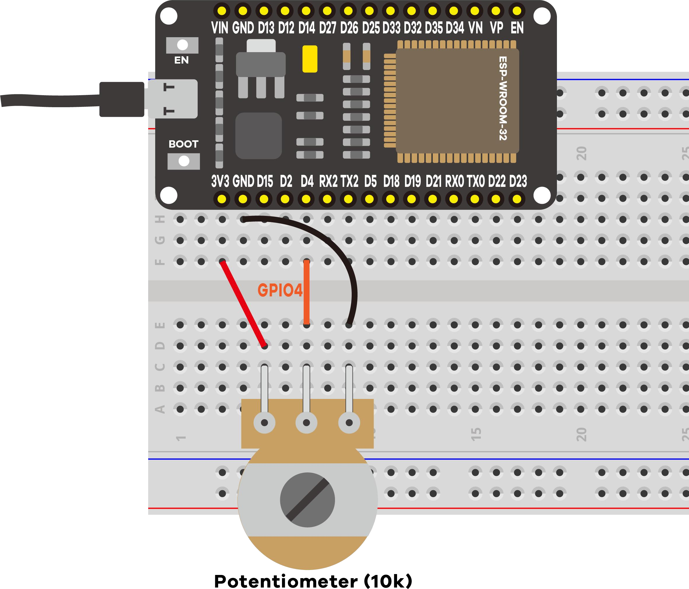
- One outer leg → 3.3 V
- Other outer leg → GND
- Middle leg (wiper) → GPIO 4
Turning the knob taps off 0 V → 3.3 V, and the ADC reports the matching 0–4095 value.
4 · Code & expected serial output
The sketch prints the raw value and the voltage it represents. Open Serial Monitor at 115200:
==============================================
 Project 2: ESP32 Analog Inputs (ADC)
==============================================
Potentiometer -> GPIO 4
12-bit ADC: 0 = 0 V ... 4095 = 3.3 V
Turn the knob and watch the value change.
----------------------------------------------
Pot:    0 / 4095   (~0.00 V)
Pot: 2047 / 4095   (~1.65 V)
Pot: 4095 / 4095   (~3.30 V)
potValue = analogRead(potPin);            // 0 .. 4095
float voltage = potValue * 3.3 / 4095.0;  // convert to volts
Try the Serial Plotter (Tools → Serial Plotter, 115200): turning the knob draws a live graph — a great way to see the analog signal.
5 · The ADC isn't perfectly linear
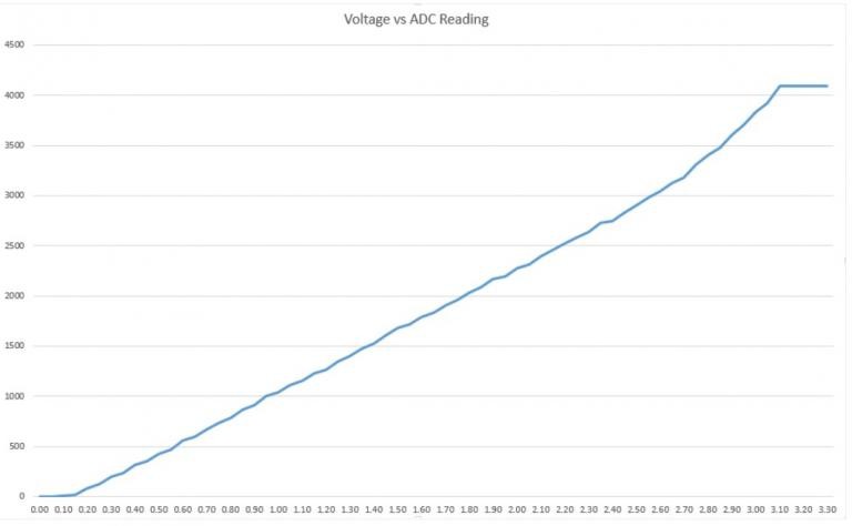
This matters for precise measurements; for a knob or light sensor it's fine.
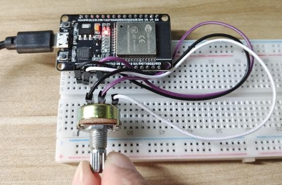
6 · Demonstration
7 · Troubleshooting
| Symptom | Likely cause | Fix |
|---|---|---|
| Stuck at 0 or 4095 | An outer leg not on 3.3 V / GND | Recheck both outer legs |
| Value jumps randomly | Wiper not on GPIO 4 | Confirm middle leg → GPIO 4 |
| Monitor blank / garbage | Wrong baud | Set it to 115200 |
| Never reaches 4095 | Normal ADC non‑linearity | Expected near the top |