Inputs & Outputs — Button → LED
Press a pushbutton → an LED turns on; release it → the LED turns off. The "hello world" of physical computing.
New here? Start with Project 0 — Introduction & Setup.
Project_1_ESP32_Inputs_Outputs.ino, then open it in the Arduino IDE (setup: Project 0b).
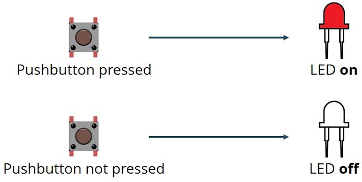
1 · What the sketch does
pinMode(buttonPin, INPUT);   // GPIO 4 — read the button
pinMode(ledPin,   OUTPUT);  // GPIO 5 — drive the LED

buttonState = digitalRead(buttonPin);
if (buttonState == HIGH) digitalWrite(ledPin, HIGH); // pressed  -> LED on
else                     digitalWrite(ledPin, LOW);  // released -> LED off
The LED lights when the pin reads HIGH, so the button sends 3.3 V to GPIO 4 when pressed, and a 10 kΩ pull‑down holds the pin LOW when released.
INPUT has no internal pull resistor, so the external 10 kΩ pull‑down is required — otherwise the pin "floats" and reads random noise. (§7 shows a software‑only alternative.)2 · The pins — analog or digital?
| Signal | GPIO | Used as | Here it is | Analog capable? |
|---|---|---|---|---|
| Button | GPIO 4 | digitalRead() | DIGITAL input | Yes — ADC2_CH0 + touch T0 (unused) |
| LED | GPIO 5 | digitalWrite() | DIGITAL output | No — no ADC (PWM only) |
Both pins are used digitally (HIGH/LOW). Use 3V3 (never 5V) for the button's HIGH side.
3 · Parts
| Qty | Part | Notes |
|---|---|---|
| 1 | ESP32 DEVKIT V1 · breadboard · jumper wires | — |
| 1 | LED | Any color — has polarity (§5) |
| 1 | 220 Ω resistor | LED limit · Red‑Red‑Black‑Black‑Brown |
| 1 | 10 kΩ resistor | Pull‑down · Brown‑Black‑Black‑Red‑Brown |
| 1 | Pushbutton | 4‑leg tactile |
4 · Wiring
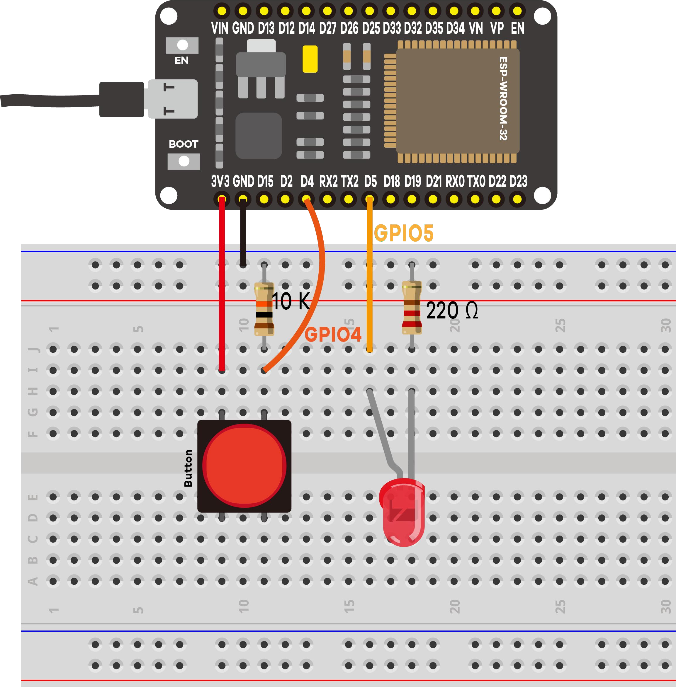
LED circuit (output, GPIO 5)
- GPIO 5 → 220 Ω → LED anode (long leg, +)
- LED cathode (short leg, −) → GND rail
Button circuit (input, GPIO 4)
- One side of the button → 3.3 V rail
- Other side → GPIO 4
- From that same GPIO 4 node → 10 kΩ → GND rail
5 · LED polarity (don't skip)
LONG leg  = Anode  (+)  -> toward the 220 Ω / GPIO 5 side
SHORT leg = Cathode (-)  -> toward GND   (flat notch on the rim = - side)
If the LED never lights, check first that it isn't reversed.
6 · Code & expected serial output
The sketch Project_1_ESP32_Inputs_Outputs.ino prints event‑based logs (only when the state changes, so the monitor stays readable). Open Serial Monitor at 115200:
========================================
 Project 1: ESP32 Inputs & Outputs
========================================
Button (input)  -> GPIO 4
LED    (output) -> GPIO 5
Press the button to turn the LED ON.
Waiting for button presses...
----------------------------------------
[EVENT] Button PRESSED  -> LED is ON
[EVENT] Button RELEASED -> LED is OFF
A 50 ms debounce delay stops one press from being logged many times.
7 · Optional — no external resistor (software pull‑up)
Wire the button between GPIO 4 and GND and enable the internal pull‑up. This inverts the logic:
pinMode(buttonPin, INPUT_PULLUP);   // reads HIGH when NOT pressed
if (buttonState == LOW) digitalWrite(ledPin, HIGH); // pressed  -> LED on
else                    digitalWrite(ledPin, LOW);  // released -> LED off
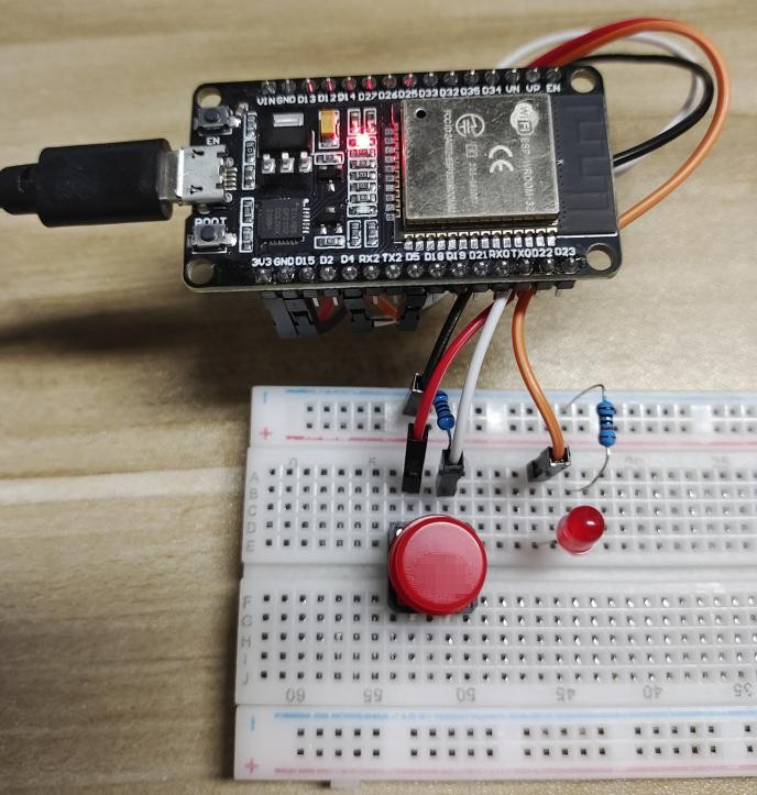
INPUT_PULLUP + flipped code. Don't mix them.8 · Demonstration
9 · Troubleshooting
| Symptom | Likely cause | Fix |
|---|---|---|
| LED never lights | LED reversed | Flip it — long leg toward the 220 Ω side |
| LED always on / flickers | Floating input (missing pull‑down) | Add the 10 kΩ from GPIO 4 to GND |
| Monitor blank / garbage | Wrong baud | Set it to 115200 |
| Button seems inverted | INPUT_PULLUP with original code | Match code and wiring (§7) |
| Nothing uploads | Charge‑only cable / wrong port | Data cable; correct port; hold BOOT |
| LED very dim | 10 kΩ in the LED path | Use 220 Ω for the LED |