Introduction, Board Tour & Setup
Kit: LAFVIN Basic Starter Kit for ESP32 · Board: ESP32 DEVKIT V1 (ESP‑WROOM‑32, 30‑pin)
The foundation for every other project: what the ESP32 is, how to read its pins, and how to upload your first sketch.
Brand new to electronics? Read Project 00 — Electronics & Communication Basics first.
1 · What is the ESP32?
The ESP32 is a low‑cost, low‑power System‑on‑a‑Chip (SoC) from Espressif. A single chip packs:
- A dual‑core 32‑bit processor (Xtensa LX6) up to 240 MHz
- Wi‑Fi (2.4 GHz) and Bluetooth (Classic + BLE)
- 520 KB SRAM and typically 4 MB flash
- ADC, DAC, PWM, I²C, SPI, UART, and capacitive‑touch peripherals
Its built‑in wireless makes it ideal for IoT — several later projects host a web server right on the board.
2 · What's in the kit
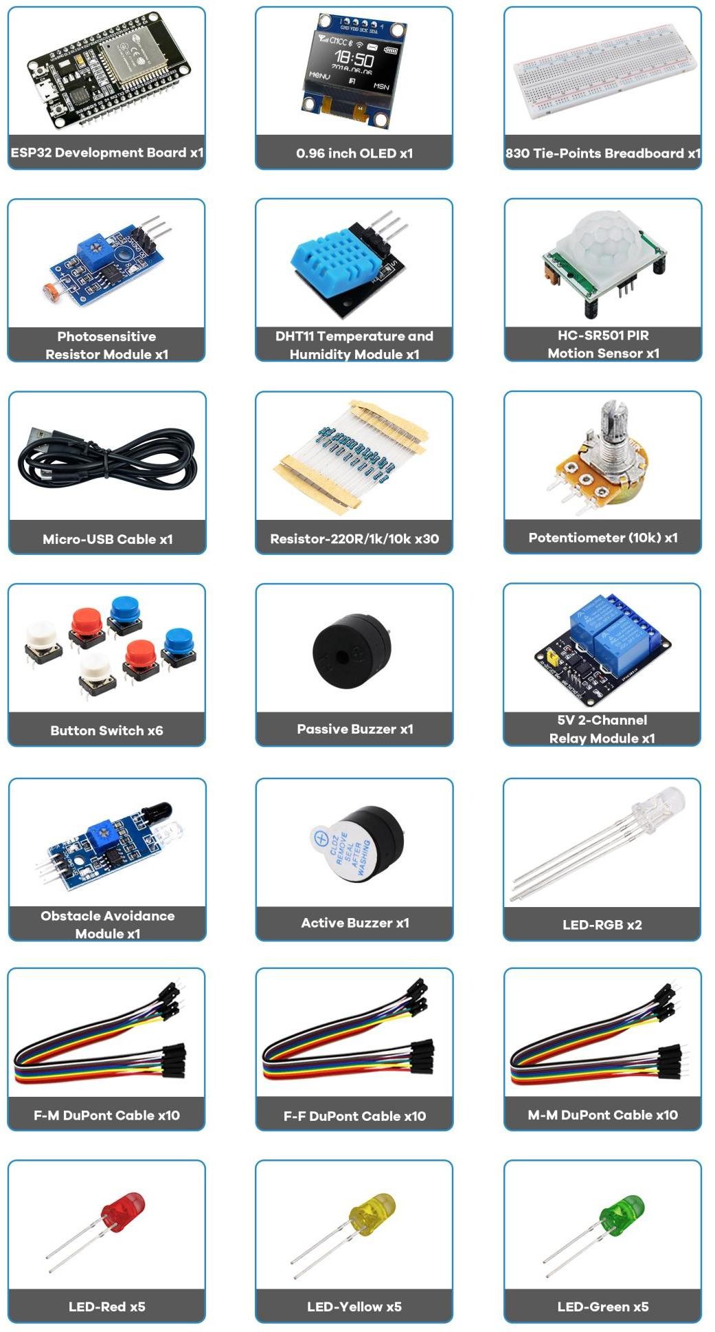
3 · Board tour
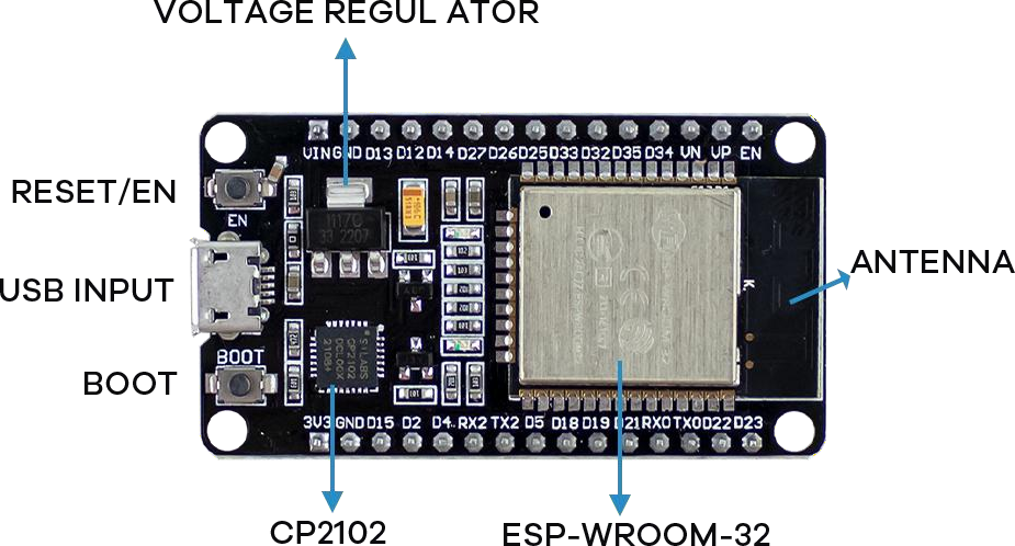
| Part | What it does |
|---|---|
| Micro‑USB port | Uploads code and powers the board. Use a data cable, not charge‑only. |
| CP2102 (USB‑to‑UART) | Bridges USB and the ESP32's serial port. Needs the CP210x driver (§8). Some boards use CH340 instead. |
| Voltage regulator | Drops 5 V (USB/VIN) to the 3.3 V the chip runs on. |
| EN / RESET | Restarts the board and runs the current sketch. |
| BOOT | Puts the chip into flashing mode (§9). |
| ESP‑WROOM‑32 | The metal module holding the chip, flash, and PCB antenna. |
| On‑board LEDs | Red = power; blue = wired to GPIO 2 for debugging. |
4 · Specifications
| Feature | Value | Feature | Value |
|---|---|---|---|
| Cores | 2 (dual) | SRAM | 520 KB |
| Clock | up to 240 MHz | Flash | 4 MB (typical) |
| Wi‑Fi | 2.4 GHz, 150 Mbps | GPIO header pins | 30 |
| Bluetooth | BLE + Classic | Logic level | 3.3 V |
| USB‑UART | CP2102 | Max current / pin | 40 mA (keep ≤ 12 mA) |
5 · The pinout
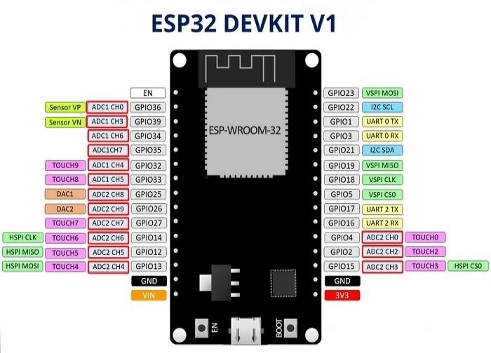
- I²C: SDA = GPIO 21, SCL = GPIO 22
- SPI (VSPI): MOSI 23, MISO 19, CLK 18, CS 5
- UART0 (USB serial): TX0 = GPIO 1, RX0 = GPIO 3
- DAC (true analog out): GPIO 25, GPIO 26
- Power:
3V3(regulated out),VIN(5 V from USB),GND
6 · Digital vs. analog — the key idea
- DIGITAL — pin is either HIGH (≈3.3 V) or LOW (0 V). LEDs, buttons, relays, buzzers.
digitalRead()/digitalWrite(). - ANALOG IN — measures a range of voltage (0–3.3 V) → a number 0–4095 (12‑bit).
analogRead(). Potentiometer, photoresistor. - ANALOG OUT — two true DAC pins (25, 26); for LEDs/motors we usually fake it with PWM (rapidly pulsing a digital pin).
Two ADC banks:
- ADC1 — GPIO 32, 33, 34, 35, 36, 39 — always usable.
- ADC2 — GPIO 0, 2, 4, 12, 13, 14, 15, 25, 26, 27 — cannot be read while Wi‑Fi is on (prefer ADC1 in Wi‑Fi projects).
7 · Which GPIOs should you use?
| Category | Pins | Notes |
|---|---|---|
| SAFE general‑purpose | 4, 13, 16, 17, 18, 19, 21, 22, 23, 25, 26, 27, 32, 33 | First choice for inputs and outputs. |
| STRAPPING | 0, 2, 5, 12, 15 | Read at boot. Usable, but a wrong level can block uploading — avoid for sensitive inputs. |
| BOOT HIGH/PWM | 1, 3, 5, 14, 15 | Pulse or go HIGH at reset — may glitch attached outputs. |
| INPUT‑ONLY | 34, 35, 36 (VP), 39 (VN) | No output, and no internal pull‑up/down. |
| DO NOT USE | 6, 7, 8, 9, 10, 11 | Wired to the internal SPI flash. |
8 · Install ESP32 support in Arduino IDE
- Install the Arduino IDE (1.8.x or 2.x).
- File → Preferences → Additional Boards Manager URLs, add:
https://raw.githubusercontent.com/espressif/arduino-esp32/gh-pages/package_esp32_index.json - Tools → Board → Boards Manager…, search esp32, install "esp32 by Espressif Systems".
- Tools → Board → select "DOIT ESP32 DEVKIT V1".
- If no port appears, install the CP210x driver (repo folder Install CP2101 drivers Windows).
- Tools → Port → choose the board's port.
9 · Uploading & the BOOT‑button trick
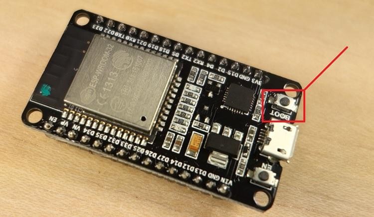
Click Upload, wait for "Done uploading.", then open Serial Monitor at 115200 baud (all our sketches use this).
If you see "Failed to connect to ESP32: … Connecting…":
- Press and hold BOOT.
- Click Upload.
- When "Connecting…" appears, release BOOT.
- After "Done uploading", press EN/RESET to run the sketch.
10 · Breadboard & power basics
- The outer rails (+ / −, red / blue) run the board's length and carry power. The inner rows connect in groups of 5, split by the center gap.
- Feed logic power from
3V3→ + rail, andGND→ − rail.
VIN, but still drive their signal pins with 3.3 V logic.Reading resistor color bands (this kit ships 5‑band ±1%)
| Resistor | Bands | Used for |
|---|---|---|
| 220 Ω | Red Red Black Black Brown | LED current limiting |
| 10 kΩ | Brown Black Black Red Brown | Pull‑down / pull‑up |
| 1 kΩ | Brown Black Black Brown Brown | General purpose |
Read with the tolerance band (Brown, ±1%) on the right. The first band gives it away — Red starts the 220 Ω; Brown starts the 10 kΩ and 1 kΩ.
11 · Next
Next, set up your software in Project 0b — Arduino IDE Setup, then build Project 1 — Inputs & Outputs (button + LED) and work up through analog input, PWM, sensors, and the Wi‑Fi web‑server projects.