Relay Web Server
Switch a relay from a web page — a tiny 3.3 V signal controlling a much larger circuit.
⬇ Download the sketch
Save
Project_7_ESP32_Relay_Web_Server.ino, then open it in the Arduino IDE (setup: Project 0b). Needs the ESPAsyncWebServer + AsyncTCP libraries and your Wi‑Fi credentials.
⚠️ Safety first. Mains voltage (120 V / 230 V) is dangerous. In this project use only low‑voltage loads (the kit's LED). Never wire mains while powered; if you're not experienced with mains, don't use it — ask someone who is.
1 · What a relay is
A relay is an electrically‑operated switch. A small coil current (from an ESP32 GPIO) flips a mechanical contact, connecting or disconnecting a separate higher‑power circuit — the two sides electrically isolated.
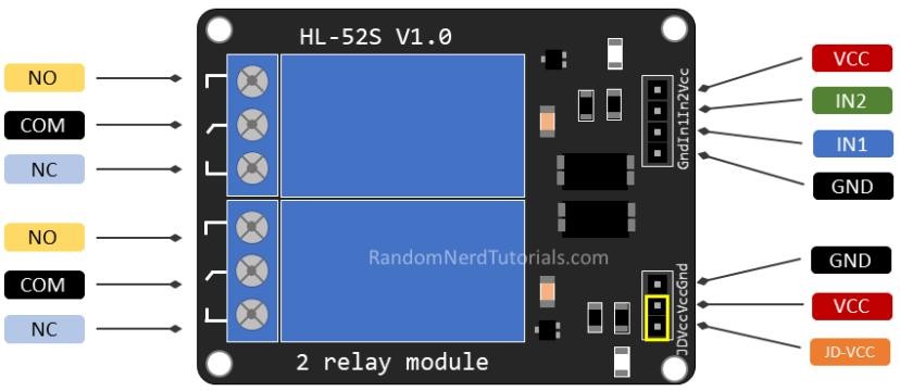
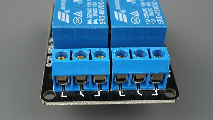
Switched side — COM / NO / NC
- COM — the wire you're switching.
- NO (Normally Open) — off until triggered → use for off by default.
- NC (Normally Closed) — on until triggered → use for on by default.
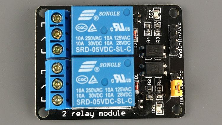
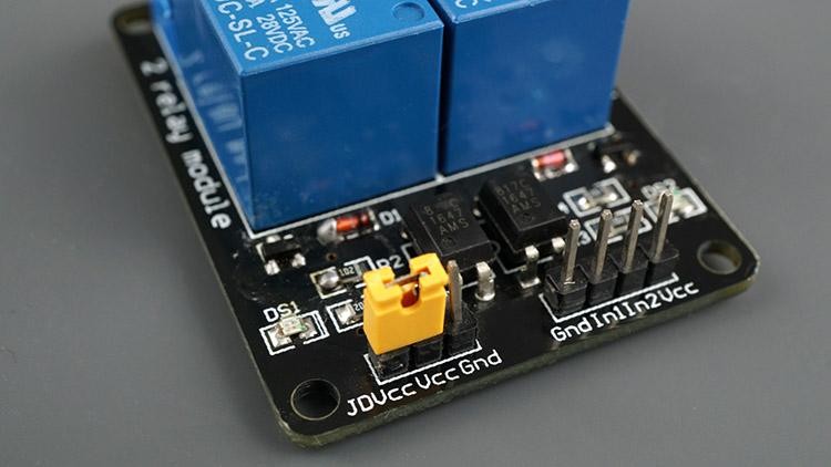
Control side — VCC / GND / IN
2 · Install the required libraries
This project uses the asynchronous server libraries — install both:
- ESPAsyncWebServer
- AsyncTCP (ESP32)
Add each via Sketch → Include Library → Add .ZIP Library…, then restart the IDE.
3 · Wiring
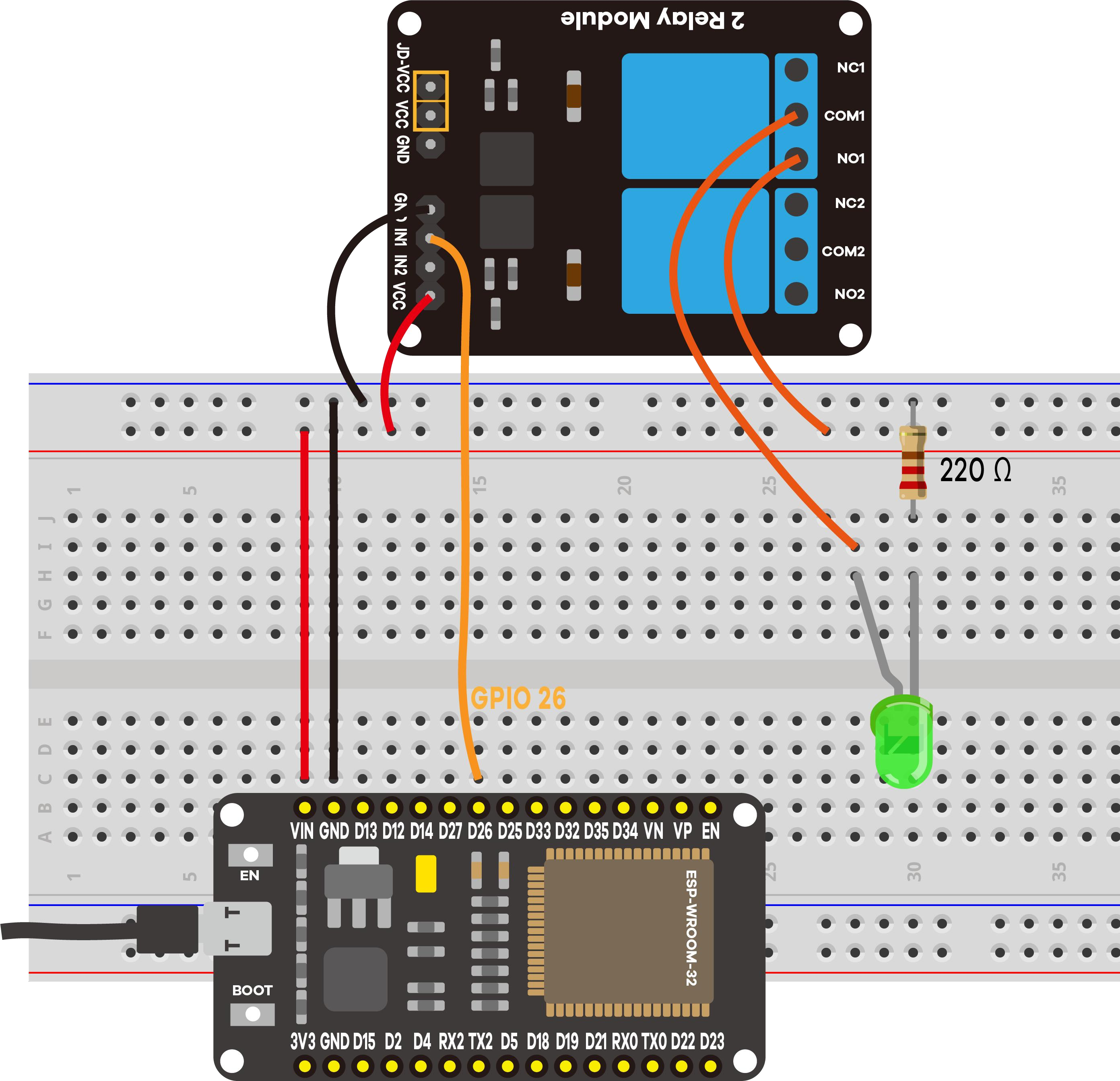
- Relay VCC → VIN (5 V) · GND → GND
- Relay IN1 → GPIO 26 (IN2 → GPIO 27 for channel 2)
- Switched side: LED (with 220 Ω) through COM → NO
4 · Upload & use
Set your Wi‑Fi credentials, upload, open Serial Monitor at 115200, press EN/RESET:
==============================================
 Project 7: ESP32 Relay Web Server
==============================================
2 relay(s), mode: Normally Open (NO)
Relay #1 -> GPIO 26
Relay #2 -> GPIO 27
Connecting to Wi-Fi: MyNetwork
....
Wi-Fi connected!
Open this address in your browser:  http://192.168.1.42
----------------------------------------------
[WEB] Relay #1 -> ON
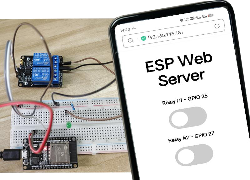
Open the address; flip a toggle → the relay clicks and the clean line above prints (the original sketch printed a cryptic NO 11).
NO‑mode note: in Normally‑Open mode the relay is off when the pin is HIGH, so the sketch writes the inverse of the requested state. That's expected.
5 · Demonstration
6 · Troubleshooting
| Symptom | Likely cause | Fix |
|---|---|---|
Compile error on ESPAsyncWebServer | Libraries missing | Install ESPAsyncWebServer and AsyncTCP |
| Relay clicks, load doesn't switch | Wired to NC | Use COM → NO |
| Toggle seems inverted | NO‑mode inversion (normal) | Leave the sketch as‑is |
| No click at all | IN mis‑wired / module unpowered | IN → GPIO 26/27; VCC→VIN, GND→GND |
| Stuck on "Connecting…" | Wrong credentials / 5 GHz | Fix credentials; use 2.4 GHz |